The formula is wrong because the current I (Fig. 3) was calculated without taking into account the resistance R.
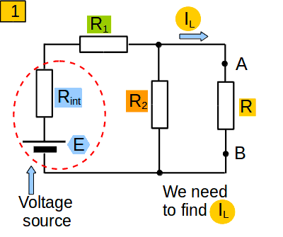
I will explain it with an example. Look at a ciruit at picture 1. E is the voltage source, and Rint is its internal resistance. We need to find the current IL, which passes through the resistance R.
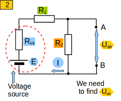
Lets make the following mental operation: remove R from the circuit (pic. 2). We need to find the voltage between points A and B (Uab). The resistance of the circuit through which current I passes, is equal to Rint+R1+ R2
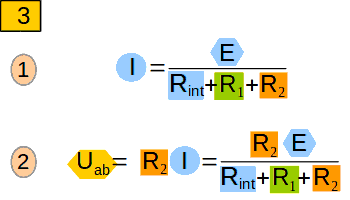
Therefore, the current I will be equal (pic. 3, 1). According to Ohm's law the voltage Uab will be equal to(see pic. 3, 2).
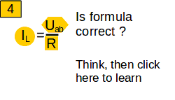
We now know the voltage Uab and the resistance R. Maybe we can calculate the current IL in accordance with Ohms law?
The formula is wrong because the current I (Fig. 3) was calculated without taking into account the resistance R.
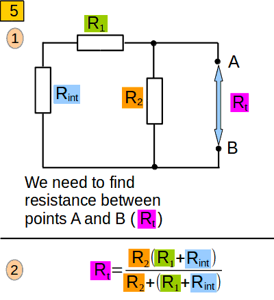
Now let us mentally replace the voltage source E with its internal resistance Rint (pic. 5, 1 ). The resistance between points A and B (we denote it as Rt) is the resistance of two parallel-connected branches: Rint+R1 and R2. It will be equal to (see pic. 5, 2)
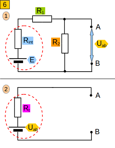
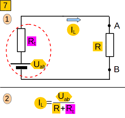
For the solution of our problem (calculate the current IL), we can consider the circuits in figure (6, 1) and (6, 2) as equivalent. This is the essence of the Thevenin theorem. That is, the entire circuit (6, 1) can be regarded as one battery with EMF Uab and internal resistance Rt. Now we can easily calculate the current IL (pic. 7, 2). The circuit in (pic. 6, 1) is very simple. But if was much more complicated, with lots of resistors and voltage sources , it could be considered as the equivalent to circuit (6, 2).
What can you do to calculate a current through a part of an electric ciruit?
Remove this part mentally, then calculate the voltage between its borders, then...
Replace mentally all voltage sources with their internal resistance, then...
Calculate the resistance between its borders. The current will be equal to ...
The current will be equal to voltage on the parts borders (after you remove it mentally), divided by the sum of resistance of the part and resistance of the remaining circuit..
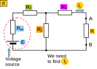
Again I explain it with an example. Look at a circuit in picture 8. Our task is to calculate current IL.
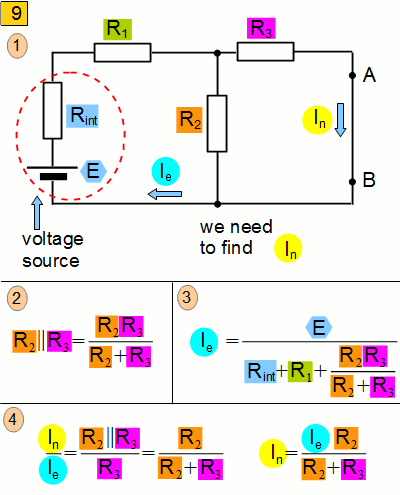
Like in Thevenin theorem, we will mentally remove resistance R. But now we will short-circuit points A and B, so that resistance between them is null (picture 9.). Let us calculate current In. To achieve that we will calculate current Ie first. In our scheme R2 and R3 are connected in parallel. Let us calculate their resistance. Then in accordance with Ohm law we find current Ie (picture. 9, 3). Then we calculate current In (picture 9, 4).
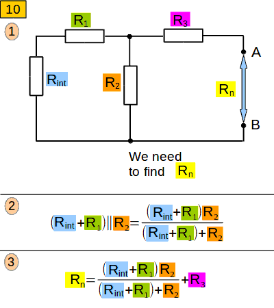
Now let us remove the jumper between A and B, and also replace voltage source E with a jumper. The internal resistance Rint will stay in place. (picture. 10, 1). We did something like this, when we learned the Thevenin theorem. Let us find resistance between points A and B. In our scheme Rint+R1 and R2 are connected in parallel. Let us find their resistance (picture 10, 2). The resistance Rn will be (see picture 10, 3).
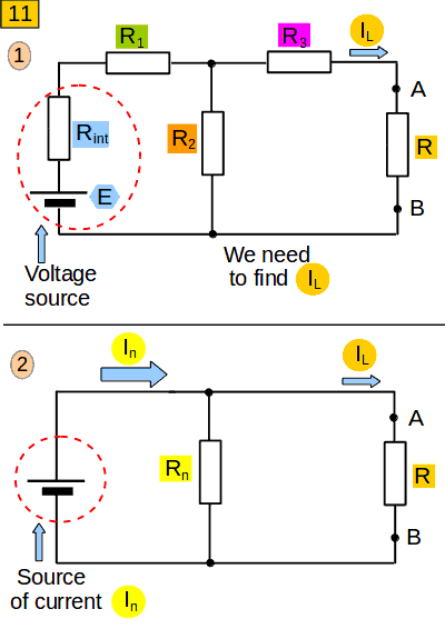
The essence of the Northon theorem is that we can replace the initial circuit (picture 11, 1) with a much simpler one (picture 11, 2). It consists, apart from the load, the current through which we want to calculate, of a current source (which produces a constant current that we have calculated) and a resistance connected in parallel to it (which we also have calculated). If the initial circuit was more complicated, with many resistors and voltage sources, it could also be replaced with scheme (11, 2)
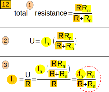
Let us calculate IL now. The total resistance of the circuit (11, 2) will be (picture 12, 1). Hence the voltage between points A and B will be (12, 2). Current IL will be (pic. 12, 3).
To calculate the current through a part of an electrical circuit one can ....
Mentally replace that part with a jumper, then calculate the current through the jumper, and then ...
Mentally remove the jumper, as well as voltage sources, but leave their internal resistancies, then ....
Calculate the resistance between the borders of the circuit. The rest of the circuit can be represented as ....
A source of current, which we have calculated, and a resistance connected in parallel to it that we have also calculated. The current will be ...
The current will be equal to the calculated resistance multiplied by the calculated current divided by the sum of the calculated resistance and load resistance.
What Thevenin and Northon theorems have in common?
With their help the current through part of a circuit can be calculated. The remaining part is simplified. What else?
In the calculations part of a circuit is mentally removed,from the remaining part all votage sources are mentally replaced by their internal resistance. Then the resistance between the boundaries of the site is calculated.
What is the difference between Thevenin and Northon theorems?
In Thevenin theorem the load is removed and the voltage between its borders is calculated. In Northon theorem the load is replaced by a bridge and and the current through the bridge is calculated. What else?
In Thevenin theorem the the remaining circuit is transformed to a voltage source with a resistance connected in series to it. In Northon theorem the remaining circuit is transformed to a current source connected in parallel with the resistance.